Phases between Command and Clock
There are seven differnet lines for the readout of the prototype tracker.
- clk: readout clock and trigger acknowledge
- select: selects if clk is used to shift out data or is interpreted as trigger
acknowledge)
- clkd: clock to enable/disable channnels to be latched into the readout buffer,
used with ddis
- ddis: bit pattern to enable/disable channels
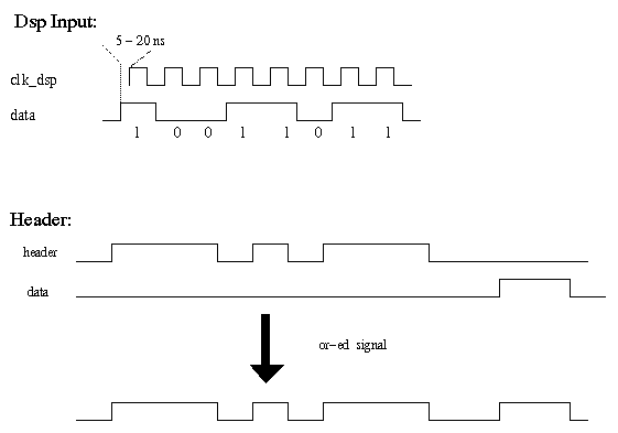
- header: header pattern to the dsp. It initiates the dsp to read in data
- clk_dsp: continues running clock to the dsp
- data: Out put data which is read by the dsp. The phase is determined by the
phase of clk.
clkd and ddis
If the six ddis lines are held high continously (no channel is disabled) there is no
phase between these two lines.
Readout
There are two phases that are important for the readout:
- Phase between header and clk
- The header is ored together with the data from the tracker.
The phase of the tracker data is determined by the clock clk.
Because header and clk run through the same cable length and
electronics the header is in phase with the data if it is
in phase with the clk.
- Phase between clk_dsp and data
- The phase between clk_dsp and data is measured at the Link inputs
of the low-level card. The rising edge of the data has to be a before the rising
edge of the clk_dsp. Typically 10-20 ns.
If the select line is toggeled before the clk is switched on, no timing
is involved for these two lines.

Readout Sequence
The following diagram shows the sequence of bits anf their timing in order to read out
the tracker. (there is also a ps version )

Last modified: Fri Jul 16 08:18:55 PDT 1999

