This page shows results that were obtained with GTFE 64c, GTRC B and hdi version 1 (used for the BTEM). The signals were measured with a scope probe connecting to the corresponding trace of GTFE 8. The ground was connected to the dgnd at the connector.
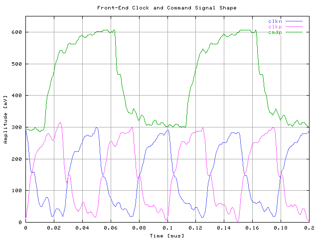
The following figure shows the clockn, clockp and commandp. The signals are AC-coupled therefore the offset of the curves is arbitrary.
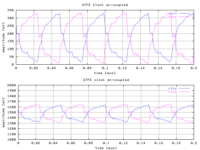
The following figure shows the clkn and clkp, but in DC couple mode so that the offset is seen.
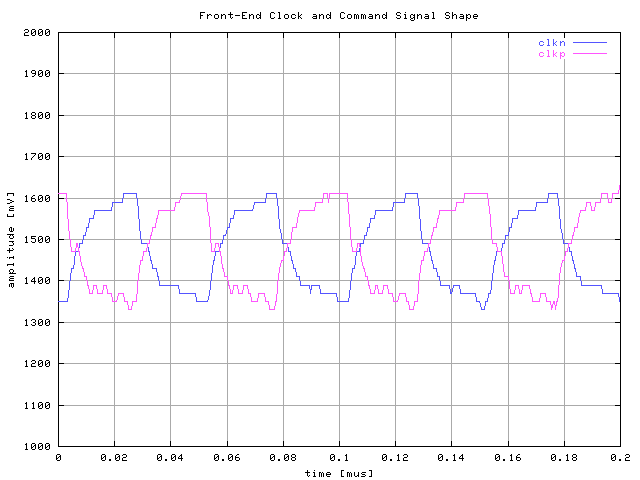
For the previous tests the clock line on the hdi was terminated with a 1K Resistor. For the measurement, shown in the following figure the termination resistor has been removed. The measurements were performed with scope probe AC and DC coupled to the scope.