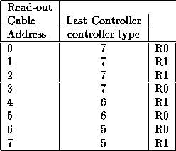
Table 1: Last Controller Address, controller type.
M. Hirayama, W. Kröger
Version 1.0
Table 1 shows for every read out cable the address of the last controller. It also lists the controller type that a cable reads.
Table 1: Last Controller Address, controller type.
The controller addresses on a cable are not consecutive any more because some trays were removed from the beam test tower. Table 2 shows the controller addresses. Position p0 is the closest to the bottom of the tracker. Cable zero to three read out seven controller whereas cable four to seven read only six controller.
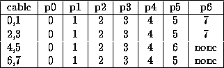
Table 2: Controller Addresses for a cable
The table 3 shows the correspondence between tracker layer, read out cable and controller address. The index is random and was chosen to have even numbers for Y-layers and odd numbers for X-layers.
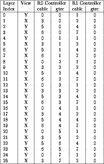
Table 3: Correspondence between tracker layer and cable/GTRC addresses.
The front end chips (GTFE) and controller chips (GTRC) have to be configured before sensible data are read out. The purpose to configure the tracker is to ensure that all layers are read out, there is a valid fastOr signal for every layer and that noisy channels are masked from the trigger (or data if required).
The following list summarizes known problems for the eight read out cables.
The two main tools to insure that the tracker is working properly are strip maps and cosmic trigger. Another possibility is to inject charges into the amplifier channels. However charge injection is more complex than simple wire maps and not discussed here.
Strip maps show the occupancy for every channel for each tracker layer. Data are collected using random trigger or particle trigger. The main purpose of the strip maps is to find noisy and dead channels. Random trigger data are taken with different thresholds.
Cosmic trigger are collected using the tracker self trigger or external scintillation counter. A single event display is needed to view the tracks. Cosmic tracks provide a rough estimation about the efficiency of the detectors.
Configuration Issues for the BFEM Tracker
This document was generated using the LaTeX2HTML translator Version 96.1-d (Mar 10, 1996) Copyright © 1993, 1994, 1995, 1996, Nikos Drakos, Computer Based Learning Unit, University of Leeds.
The command line arguments were:
latex2html -split 0 config.tex.
The translation was initiated by Wilko Kroeger on Wed Jan 24 14:37:53 PST 2001