Markarian 501- First Look
Gus Sinnis
9/21/1997
Map of Smoothed Excess: Mrk 501
This memo describes the results of a first look at Mrk501 with Milagrito. The data set consists of 7 days in March, April, and May that Whipple, HEGRA, and CAT measured a high flux from Mrk501. The reconstruction code used is described in a previous memo. The analysis code used is adapted from my old CYGNUS code and uses "time-sloshing" to determine the background. The formula of Li and Ma is used to determine the significance of any excess. I have used this subset of our data to try to determine the following parameters:
The data-set:
The figure below shows the fluxes from Mrk 501 measured by Whipple, CAT, and HEGRA.
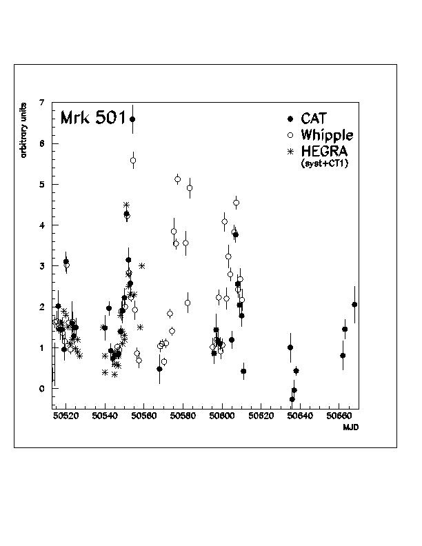
This plot was obtained from Michael Punch of CAT and is NOT to be distributed. The idea was to use half of the data set to perform the trials necessary to answer the above questions and the second half to verify that I was not simply tuning on noise. With this in mind the top 10 days in March, April, and May were stripped. Due to various problems with the experiment, we ended up with 7 days of good data. The table below gives the exact dates in the data-set along with the start time of the "source day" (The time that the source is at the nadir), and the number events in the background bin for that day (with a cut of NFIT > 20 and a bin 1.4 degrees wide in DEC and 1.4/cos(39.8) in RA).
| 4/14/97 | 10:30 | 2174 |
| 4/16/97 | 10:22 | 2217 |
| 5/07/97 | 8:59 | 2252 |
| 5/08/97 | 8:55 | 1353 |
| 5/09/97 | 8:51 | 2188 |
| 5/10/97 | 8:47 | 213 |
| 5/11/97 | 8:44 | 2255 |
| 5/12/97 | 8:40 | 2239 |
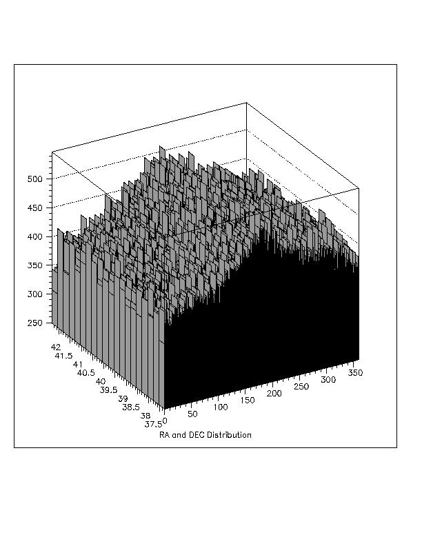
The figure below shows the entire DEC band around Mrk 501. One can see that the background is non-uniform, peaking at a RA of about 200 degrees. The J2000 of Mrk 501 are (39.8 DEC, 253.5 RA).
The Analysis:
Our event rate within the DEC band is about 24 Hz. To obtain the background in the "source" bin I associate each real event with the times of 10 other events in the DEC band. The 10 times are chosen from a buffer that spans 200,000 events or 2 hours (which ever comes first) around the true event. I then look at the excess in the source bin and 32 surrounding bins (+- 5 bins in RA and +-1 bin in DEC). These bins are used to ensure the integrity of the method.
The table below gives the results for the bin centered on Mrk 501 for various NFIT cuts.
| NFIT | ON Source | Off Source | Li-Ma Sigma |
| >20 | 13481 | 136276 | -1.2 |
| >30 | 7049 | 71807 | -0.67 |
| >35 | 5809 | 58324 | -0.29 |
| >40 | 4844 | 48935 | -0.68 |
| >50 | 3533 | 35540 | -0.34 |
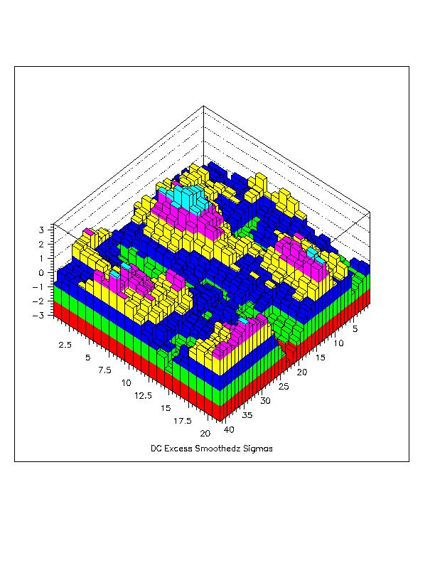
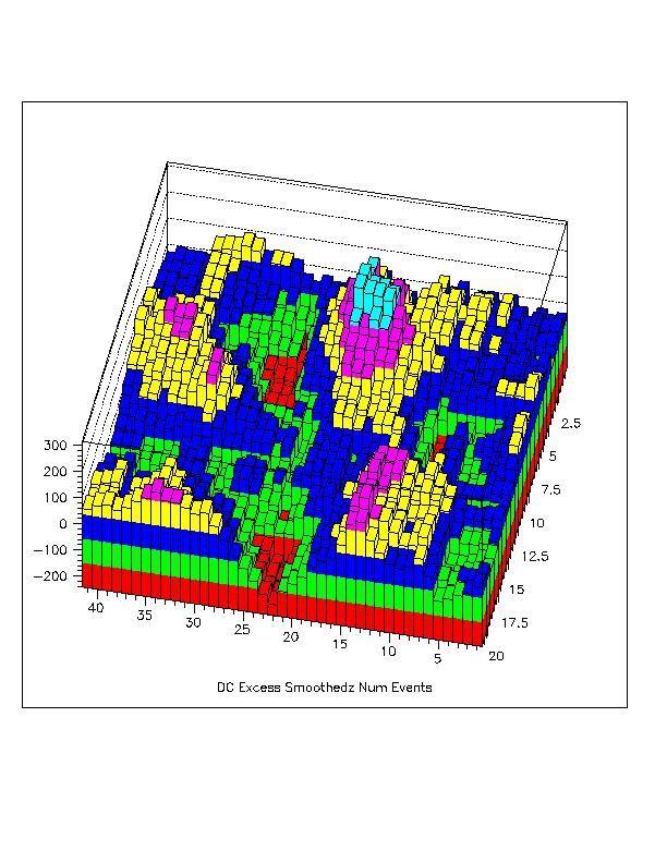
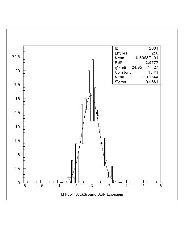
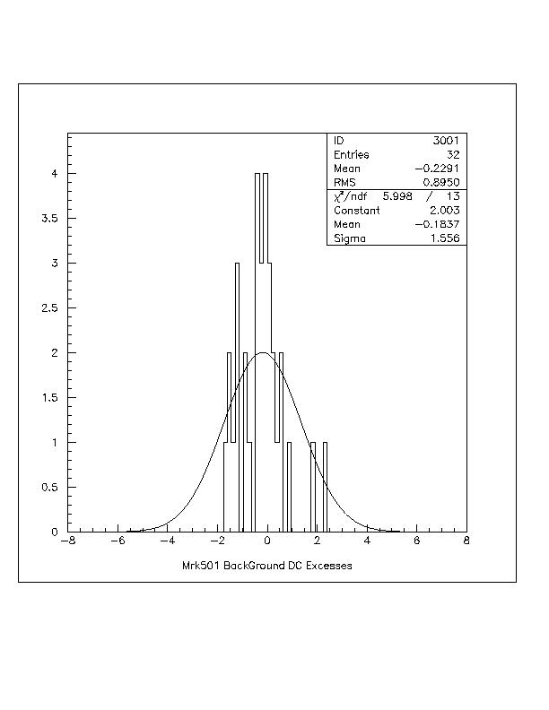
The figures below show the distribution of DC and daily excesses for the background bins around Mrk501.
To investigate any systematic pointing error I moved the position of Mrk 501 in 3 different directions: +0.7 degrees in DEC, +0.7/cos(39.8) degrees in RA, and then shifted in both RA and DEC at the same time. By examining the neighboring bins in each of these trials, I can look for a systematic in any direction. (0.7 degrees corresponds to ½ the bin width.) Based on the meager results in the table above, I performed this offset search with the requirement NFIT > 40.
The "signal" maximized for the following offsets: DEC Mrk = 39.0, RA Mrk = 252.5. The figure below shows the map of the excesses for all 33 bins examined for this choice of source coordinate.
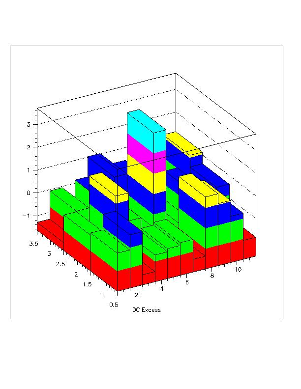
The excess for the source bin was ON= 5229, OFF= 49524, and Sigma = 3.71.This was the largest excess (or deficit) observed for any of the 33 bins in any of the trials I performed. The probability of exceeding 3.7 sigma is 10-4. I performed fewer than 10 trials (not independent!) to arrive at this result. While this is not an overwhelming signal, I think there is a reasonable chance that we have observed gamma rays from Mrk 501. Certainly, it is worth examining the remainder of the data set with this set of cuts and offsets to verify or refute this effect.
More Trials:
To better understand the signal and optimally choose the criteria for any further searches I again varied NFIT, and varied the bin size (while centered at the position found above). The table below gives the results.
| Bin Size | NFIT | Sigma |
| 1.8 | >40 | 3.3 |
| 1.8 | >30 | 2.0 |
| 1.6 | >40 | 3.5 |
| 1.5 | >40 | 3.4 |
| 1.4 | >50 | 3.2 |
| 1.4 | >40 | 3.7 |
| 1.4 | >30 | 2.6 |
| 1.3 | >40 | 3.0 |
| 1.2 | >40 | 2.5 |
As expected for a true signal the excess drops off rapidly if the bin is too small, but slowly if the bin is too large. The optimal bin is the first one selected: NFIT > 40, Bin Size = 1.4 degrees. (A 1.4 degree bin corresponds to 0.5 degree angular resolution.) Note that with this selection of NFIT we keep only 35% of the events, thus if another fitting procedure can maintain this angular resolution for the smaller showers we would have a 6 sigma excess.
Discussion:
We appear to have a marginally significant excess close to the true location of Mrk 501 during 7 days in 1997 when air Cerenkov experiments measured large fluxes from this source. I still want to try several other tests with this data set: use a curvature correction derived from the Monte Carlo (we see no evidence of curvature in the data), and try several small modifications to the reconstruction algorithm. These tests should be complete be the end of this week. At that time I would like to look at the second half of the summer to verify or refute the above effect. Please send me your comments and feelings about this request. I would like to have a group consensus before proceeding to look at the remaining data.
Appendix A:
Bob Ellsworth has suggested that perhaps we are using too small a bin and do not have a systematic offset. Given the significance of the surrounding bins this does not appear likely, but below I investigate the significance of the signal at the true position of Mrk501 as a function of the bin size. The data set is missing 1 day relative to the above analysis due to limited disk space here at LANL.
| Bin Size | NFit | Sigma |
| 0.8 | >40 | -0.42 |
| 1.2 | >40 | -0.37 |
| 1.4 | >40 | -0.68 |
| 1.8 | >40 | 0.20 |
| 2.2 | >40 | 0.02 |
Appendix B:
Gaurang has suggested that around the offset bin position I did sample large enough values for the bin size for smaller values of NFIT. In the table below I investigate the effect of bin size for NFITS of >20 and >30.
| Bin Size | NFIT | Sigma |
| 1.4 | >40 | 3.9 |
| 1.4 | >30 | 2.12 |
| 1.8 | >30 | 1.59 |
| 2.0 | >30 | 0.86 |
| 2.2 | >30 | 0.92 |
| 2.4 | >30 | 0.83 |
| 2.6 | >30 | 1.0 |
| 2.8 | >30 | 1.3 |
Below I show 2 Figures that should alos dispel any doubts about what we are seeing. They are just 2 different views of the same plot. The plot is made by binning the region around Mrk501 into 0.2 degree bins. The total ON Source and OFF Source is stored in these 0.2 degree bins. This data is then smoothed by summing the 0.2 degree bins to make 1.4 degree (square) bins. What is plotted in the excess in each 1.4 degree binned that is centered on each 0.2 degree bin. The first plot is number of excess events and the second is number of sigmas.